
 EN
EN
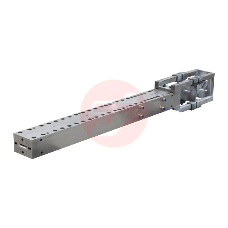
Selecting the right carbon fiber mold for wind turbine beam manufacturing is one of the most consequential decisions an engineering team will make during the production design phase. Wind turbine blades and structural beams demand exceptional dimensional accuracy, long service life, and consistent mechanical performance under extreme environmental loads. The mold technology you choose directly determines whether your production process will achieve those standards reliably at scale. With the wind energy sector accelerating its push toward longer, lighter, and more aerodynamically efficient blade designs, the demand for high-performance carbon fiber mold solutions has never been more critical.
A carbon fiber mold designed specifically for wind turbine beam applications must handle complex geometry, resist thermal cycling, maintain tight tolerances over thousands of production cycles, and support efficient demolding without structural compromise. This article walks through the essential selection criteria, key technical parameters, and practical considerations that engineering and procurement professionals must evaluate when choosing a carbon fiber mold for this demanding application. Whether you are setting up a new production line or upgrading an existing one, this guide is designed to give you a clear, structured decision framework.
Understanding the Role of a Carbon Fiber Mold in Wind Turbine Beam Production
Why the Mold Is the Foundation of Structural Performance
In wind turbine beam manufacturing, the carbon fiber mold is not simply a shaping tool — it is the geometric and structural blueprint from which every beam is replicated. Any deviation in mold geometry, surface quality, or thermal expansion behavior will be transferred directly into the finished composite part. This means that beam stiffness, fiber alignment accuracy, and fatigue resistance all begin with the quality of the mold itself.
The spar cap and shear web beams inside a wind turbine blade are load-bearing components subject to millions of stress cycles over a 20–30 year operational lifespan. A carbon fiber mold that cannot maintain dimensional stability under repeated heating and cooling cycles will gradually introduce cumulative geometric errors, leading to rejection rates that erode production economics. For this reason, mold selection must be treated as an engineering decision, not merely a procurement one.
Structural integrity of the beam also depends on the mold's ability to maintain a consistent internal cavity profile across its full length — which can exceed 20 meters on modern turbine designs. Long-span carbon fiber mold systems must be engineered with built-in stiffening structures to prevent sagging, warping, or differential thermal deformation that would otherwise compromise beam straightness and fiber-to-resin volume ratios.
The Connection Between Mold Type and Manufacturing Process
Wind turbine beam components are most commonly produced through pultrusion, resin transfer molding (RTM), or vacuum infusion processes. Each process imposes distinct requirements on the carbon fiber mold in terms of cavity pressure resistance, surface release characteristics, and thermal management capability. Pultrusion tooling, for example, demands that the mold endure continuous through-die loading forces while maintaining a precisely shaped cross-section, making material stiffness and surface hardness primary selection criteria.
An RTM carbon fiber mold must be engineered as a closed, two-part tool capable of sealing consistently under injection pressure. This requires flange geometry that ensures repeatable closing force distribution, sealing surfaces that resist resin infiltration, and matched halves that maintain cavity dimensions despite thermal expansion during the cure cycle. Understanding which manufacturing process will use the mold is therefore the essential first question before evaluating any other technical parameter.
For vacuum infusion processes commonly used in large-span beam manufacturing, the carbon fiber mold must provide an airtight base surface with adequate stiffness to resist atmospheric pressure loading without deflection. The mold surface must also be chemically compatible with the release agents and infusion resins used in the system, as incompatible surface coatings can cause adhesion failures or surface porosity in the final part.
Key Technical Criteria for Selecting a Carbon Fiber Mold
Material and Layup Architecture of the Mold Itself
The mold body of a high-performance carbon fiber mold for wind turbine beam production is itself a composite structure, typically built from multiple plies of carbon fiber prepreg or infused carbon fiber fabric over a tooling plug. The laminate architecture of the mold determines its coefficient of thermal expansion (CTE), bending stiffness, and long-term dimensional stability. A well-engineered carbon fiber mold will be designed with a CTE closely matched to the composite beam being manufactured, minimizing residual stress during cure and improving geometric accuracy of the finished part.
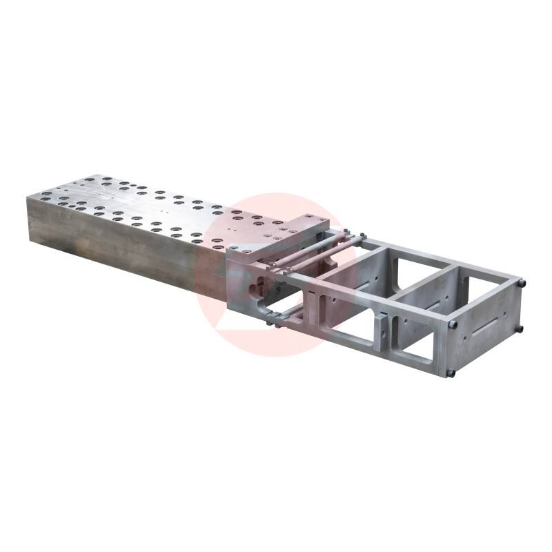
The choice between standard modulus and intermediate modulus carbon fiber reinforcements in the mold laminate affects both the tool's stiffness-to-weight ratio and its cost. For long-span wind turbine beam molds where deflection under self-weight is a real concern, higher-modulus carbon fiber reinforcements combined with a thick core structure are often necessary. The mold face coat — the surface layer that contacts the composite beam — should use a hard, abrasion-resistant resin system capable of maintaining surface roughness specifications over the tool's intended production life.
It is also important to consider whether the mold will be used in an autoclave, oven-cured, or room-temperature cure environment. Each thermal processing condition places different demands on the mold's resin system and structural layup. A carbon fiber mold intended for autoclave use must be qualified to withstand the combination of elevated temperature and positive pressure that characterizes autoclave processing, requiring a higher-temperature resin system and careful void-free laminate consolidation during manufacture.
Geometric Precision and Surface Quality Standards
For wind turbine beam applications, dimensional tolerance of the carbon fiber mold cavity is typically specified in fractions of a millimeter across the full part length. Achieving these tolerances requires a precision-machined or carefully controlled layup master pattern, accurate transfer of geometry to the mold surface, and validation of the finished mold using three-dimensional scanning or coordinate measurement techniques. Any supplier providing a carbon fiber mold for this application should be able to provide dimensional verification documentation confirming conformance to the engineering drawing.
Surface roughness of the mold face is directly reflected in the surface quality of the demolded beam. Wind turbine beam surfaces must meet aerodynamic smoothness standards in exposed areas and bonding surface quality requirements at structural join regions. A high-quality carbon fiber mold should deliver a surface finish in the Ra 0.4 to Ra 0.8 micrometer range without additional post-processing, which minimizes secondary finishing operations and reduces overall production cycle time.
Gelcoat or surface film systems applied to the mold face during manufacture should be selected for durability under repeated thermal cycling, solvent resistance from cleaning agents, and compatibility with the release systems used. An inferior surface preparation on the carbon fiber mold is one of the most common root causes of early surface degradation and reduced production shot counts, making surface engineering a critical evaluation criterion during mold qualification.
Structural Design and Thermal Management Features
Integrated Heating and Cooling Systems
Modern wind turbine beam production operates on tight cycle times, requiring rapid and uniform heating of the composite layup to cure temperature followed by controlled cooling before demolding. A carbon fiber mold designed for high-volume production should incorporate an integrated heating system — most commonly embedded electrical heating elements or fluid-circulating circuits — that delivers uniform temperature distribution across the entire mold surface. Temperature gradients within the mold during cure are a leading cause of residual stress and warpage in the finished beam, so thermal uniformity is a non-negotiable performance requirement.
The thermal management design of the carbon fiber mold must also consider the heat capacity and thermal conductivity of the mold structure itself. Carbon fiber composite mold materials have low thermal conductivity compared to metals, which can be advantageous for minimizing heat loss to the environment but can also create localized hot or cold zones if the heating circuit layout is not carefully engineered. Computational thermal analysis during mold design is a valuable tool for identifying potential temperature non-uniformities before the mold is built.
For large-format wind turbine beam molds, zonal temperature control — where different sections of the mold surface are independently controlled — is often necessary to compensate for variations in cross-sectional thickness along the beam length. This level of thermal management sophistication should be a key evaluation point when reviewing carbon fiber mold specifications from potential suppliers or when designing a custom tooling solution for a new production program.
Supporting Structure and Long-Span Stiffness Design
A carbon fiber mold for wind turbine beam manufacturing is often a large, elongated structure that must be supported at multiple points along its length without introducing unwanted deflection or local stress concentrations. The design of the mold cradle or support structure is therefore an integral part of the overall tooling system, not an afterthought. Poorly supported molds will sag over time, particularly when subjected to repeated heating and cooling cycles, producing beams with gradually increasing straightness deviations.
The mold backing structure — the load-bearing framework behind the carbon fiber face shell — is typically fabricated from steel or a combination of steel and composite materials. This structure must be designed to transfer support loads uniformly into the mold face without point-loading that could cause local deformation. The interface between the carbon fiber mold face and its backing structure must also accommodate differential thermal expansion, usually through a system of bonded or mechanically fastened connections engineered with appropriate compliance.
Evaluating the long-span stiffness design of a carbon fiber mold before purchase or fabrication approval requires requesting structural analysis documentation from the mold designer. Finite element analysis results showing deflection under self-weight and under process loading conditions give engineering teams confidence that the mold will perform to specification over its intended service life. Insisting on this level of engineering documentation is a mark of a mature tooling procurement process.
Production Life, Maintenance, and Total Cost of Ownership
Shot Count Expectations and Factors That Reduce Mold Life
A well-designed and properly maintained carbon fiber mold for wind turbine beam production should be capable of delivering between 500 and 2000 production cycles depending on the process conditions, resin system aggressiveness, demolding forces, and maintenance practices applied. Understanding the expected shot count for your specific application allows you to calculate the amortized tooling cost per beam, which is an essential input into production economics modeling when comparing tooling investment options.
The factors most likely to reduce the service life of a carbon fiber mold include mechanical damage during demolding, surface degradation from inadequate release agent application, thermal shock from rapid temperature changes, and chemical attack from residual resin or cleaning solvents. Establishing a documented mold maintenance protocol — including regular surface inspection, localized repair procedures for minor damage, and scheduled resurfacing intervals — is essential for maximizing the return on investment in carbon fiber mold tooling.
It is also important to evaluate the repairability of a carbon fiber mold before committing to a specific design. Some mold architectures allow damaged surface sections to be ground back, refilled, and re-polished to restore dimensional accuracy, while others may require complete face laminate replacement if damage penetrates beyond the gelcoat layer. Choosing a carbon fiber mold with a design that supports field repair rather than full replacement can significantly reduce lifecycle tooling costs for high-volume wind turbine beam production programs.
Evaluating Suppliers and Technical Support Capabilities
Choosing a carbon fiber mold is not only a technical decision about the tool itself — it is also a decision about the supplier relationship and ongoing technical support that will accompany the mold throughout its service life. A capable carbon fiber mold supplier should be able to provide engineering analysis documentation, dimensional verification reports, process qualification test results, and a clear statement of mold warranty terms. These documents demonstrate the supplier's technical capability and provide the manufacturing team with the reference data needed for process setup and ongoing quality control.
Technical support capabilities are particularly important for wind turbine beam production programs, where any unplanned mold-related production stoppage has significant cost implications. A supplier who can provide rapid remote diagnostics, maintain a stock of critical spare components, and dispatch a field service team for on-site repair support provides substantially more value than one offering only the mold hardware at a lower initial price. Total cost of ownership thinking should weight these service factors appropriately when making the final selection decision.
For teams seeking a proven carbon fiber mold solution engineered specifically for wind power structural beam applications, evaluating suppliers with demonstrated experience in wind energy pultrusion tooling is an important step in reducing technical and schedule risk for your production program. Verified production references in the wind energy sector give confidence that the mold design has been validated under realistic manufacturing conditions.
FAQ
What is the typical dimensional tolerance achievable with a carbon fiber mold for wind turbine beam production?
A well-engineered carbon fiber mold for wind turbine beam manufacturing can maintain dimensional tolerances within ±0.2 mm to ±0.5 mm across the mold cavity, depending on the length and complexity of the beam cross-section. Achieving these tolerances consistently requires a precision master pattern, careful laminate consolidation during mold fabrication, and verification of the finished mold using three-dimensional scanning or coordinate measurement technology before the tool enters production.
How many production cycles can a carbon fiber mold for wind turbine beams realistically achieve?
Under normal operating conditions with proper maintenance and release agent protocols, a high-quality carbon fiber mold used in wind turbine beam production can achieve between 500 and 2000 production cycles. The actual shot count will depend on process aggressiveness, demolding forces, thermal cycling conditions, and the quality of routine maintenance performed. Molds that receive scheduled surface inspections and timely minor repairs consistently outperform those used without a structured maintenance program.
Is a carbon fiber mold better than a steel mold for wind turbine beam manufacturing?
Carbon fiber molds offer significant advantages over steel molds for wind turbine beam production, including much lower weight for easier handling, a coefficient of thermal expansion that more closely matches the composite beam being produced, and faster thermal response for reduced cycle times. However, steel molds offer greater impact resistance and can be more cost-effective for very long production runs where mechanical durability is the primary concern. The best choice depends on production volume targets, dimensional requirements, process temperature, and available facility infrastructure.
What maintenance practices extend the service life of a carbon fiber mold in wind turbine beam production?
Extending the service life of a carbon fiber mold requires consistent application of appropriate release agents before each production cycle, regular visual and dimensional inspection of the mold surface, prompt repair of any surface chips or cracks before they propagate, careful handling during demolding to avoid mechanical impact, and periodic deep cleaning to remove resin residue without using solvents incompatible with the mold resin system. Maintaining a mold log that records cycle count, surface conditions, repairs, and resurfacing events provides the data needed to plan proactive maintenance and avoid unexpected production disruptions.
Table of Contents
- Understanding the Role of a Carbon Fiber Mold in Wind Turbine Beam Production
- Key Technical Criteria for Selecting a Carbon Fiber Mold
- Structural Design and Thermal Management Features
- Production Life, Maintenance, and Total Cost of Ownership
-
FAQ
- What is the typical dimensional tolerance achievable with a carbon fiber mold for wind turbine beam production?
- How many production cycles can a carbon fiber mold for wind turbine beams realistically achieve?
- Is a carbon fiber mold better than a steel mold for wind turbine beam manufacturing?
- What maintenance practices extend the service life of a carbon fiber mold in wind turbine beam production?