
 EN
EN
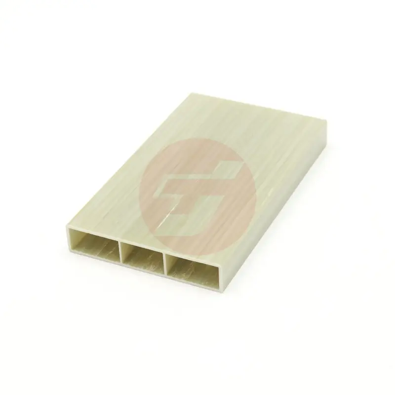
In composite manufacturing, the quality of the final product depends on numerous factors, but few are as critical as the precision and functionality of the mold design itself. From aerospace components to automotive parts and industrial equipment, the mold serves as the foundational template that determines dimensional accuracy, surface finish, fiber alignment, and structural integrity. Understanding how mold design directly influences manufacturing outcomes enables engineers and production managers to make informed decisions that reduce defects, optimize cycle times, and ensure consistent quality across production runs.
The relationship between mold design and composite quality is rooted in the mechanics of resin flow, thermal distribution, fiber orientation control, and demolding dynamics. A well-engineered mold anticipates these physical phenomena and incorporates features that guide material behavior predictably throughout the curing process. Conversely, poorly conceived mold geometries introduce variables that manifest as voids, delaminations, warping, and surface imperfections. This article explores the specific mechanisms through which mold design parameters control composite manufacturing output quality, providing actionable insights for improving process reliability and part performance.
Thermal Management and Cure Uniformity in Mold Design
How Thermal Conductivity of Mold Materials Affects Curing
The thermal properties of the mold material directly govern how heat is transferred to the composite laminate during the curing cycle. Metals such as aluminum and steel offer high thermal conductivity, enabling rapid and uniform heat distribution across the mold surface. This uniformity is essential for achieving consistent crosslinking of resin matrices, which in turn determines mechanical properties and dimensional stability. When mold design incorporates materials with mismatched thermal conductivities, temperature gradients develop across the part, leading to differential cure rates that cause internal stresses and warping.
Mold design must account for the specific thermal profile required by the resin system in use. Epoxy systems, for instance, often require controlled heating ramps and precise hold temperatures to avoid exothermic runaway or incomplete polymerization. The thickness and mass distribution of the mold influence its thermal inertia, affecting how quickly it responds to temperature changes. Engineers frequently optimize mold design by integrating heating channels or cartridge heaters to achieve active temperature control, ensuring that every region of the composite reaches the target cure temperature simultaneously.
Advanced mold design approaches utilize thermal simulation software to predict temperature distributions and identify potential hotspots or cold zones before fabrication. By modeling heat flow through the mold geometry, designers can adjust wall thickness, add insulation layers, or reposition heating elements to eliminate thermal inconsistencies. This proactive approach to mold design minimizes trial-and-error iterations and accelerates the qualification of new tooling for production environments.
Impact of Mold Thermal Expansion on Part Tolerances
Every material expands when heated, and the coefficient of thermal expansion becomes a critical consideration in mold design for composites. The mold must expand at a rate compatible with the composite laminate to prevent shear stresses at the interface during cure. If the mold design features materials with significantly higher thermal expansion than the curing composite, the part may experience compression during heating and tension during cooling, leading to microcracking or fiber distortion.
Precision mold design accounts for thermal expansion by selecting tooling materials with coefficients that closely match the composite system or by compensating dimensions to accommodate predictable expansion. For high-temperature cure cycles, invar or carbon tooling may be specified due to their low expansion characteristics. The mold design must also consider the geometry of complex parts, where differential expansion in different sections can induce bending moments or localized deformation.
Dimensional control in composite manufacturing relies heavily on how the mold design manages thermal cycling. Parts that require tight tolerances benefit from mold designs that incorporate temperature-compensating features such as adjustable clamps or spring-loaded elements that maintain consistent pressure throughout the thermal cycle. These design considerations ensure that final part dimensions remain within specification regardless of thermal fluctuations during processing.
Resin Flow Control Through Mold Geometry
How Mold Surface Texture Influences Resin Impregnation
The surface finish of the mold directly affects how resin wets out fiber reinforcements and flows through the laminate stack. In processes like resin transfer molding or vacuum-assisted resin infusion, mold design determines the pathways available for resin advancement and the resistance encountered during impregnation. A polished mold surface minimizes friction and promotes smooth resin flow, reducing the likelihood of dry spots or voids that compromise structural integrity.
Mold design must balance surface smoothness with the need for adequate resin retention in critical areas. Textured regions can be strategically incorporated into the mold design to slow resin advancement in thick sections, allowing thinner areas to fill completely before gelation begins. This controlled flow management prevents race-tracking along preferential paths and ensures uniform fiber wet-out across the entire part geometry.
Advanced mold design incorporates flow simulation data to predict resin progression through complex geometries. Computational fluid dynamics modeling reveals how mold features such as ribs, recesses, and draft angles influence fill patterns. By optimizing mold design based on these simulations, manufacturers can position injection ports and vents to achieve complete filling with minimal resin waste and reduced cycle times.
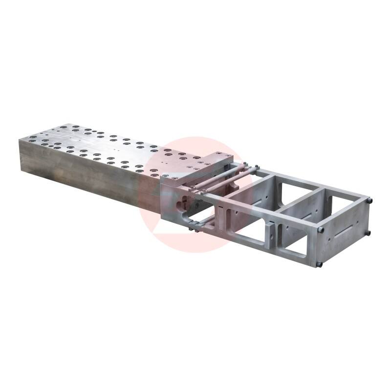
Vent Placement and Air Evacuation in Mold Design
Trapped air represents one of the most common defects in composite manufacturing, and mold design plays a decisive role in preventing void formation. Vents must be strategically positioned at high points and terminal flow regions where air naturally accumulates during resin infusion. The size, spacing, and configuration of vents in the mold design determine evacuation efficiency without allowing excessive resin bleed.
Effective mold design incorporates multiple vent strategies tailored to part geometry and process parameters. Porous inserts, breather fabrics, and machined grooves each serve specific functions in air removal. The mold design must ensure that vent paths remain open throughout the filling process, which requires careful consideration of how consolidation pressure affects gap dimensions and flow resistance.
For complex three-dimensional geometries, mold design often includes secondary venting systems that address internal cavities or undercut features. These supplementary vents prevent air entrapment in difficult-to-reach zones that could otherwise compromise part quality. The integration of vacuum monitoring ports into the mold design allows real-time assessment of evacuation effectiveness, enabling process adjustments that maintain consistent void content below acceptable thresholds.
Fiber Orientation Control and Mold Geometry
How Mold Contours Guide Fiber Placement
The three-dimensional shape defined by mold design dictates how continuous fibers drape over surfaces and conform to compound curves. Accurate fiber orientation is essential for achieving the mechanical properties predicted by composite design calculations. Mold design must accommodate fiber steering requirements while avoiding features that cause wrinkling, bridging, or excessive shear deformation in the reinforcement fabric.
In hand layup and automated fiber placement processes, mold design provides the physical reference for each ply's position and orientation. Sharp radii or abrupt transitions in the mold geometry force fibers to compress or stretch beyond their natural draping limits, creating defects that reduce load-bearing capacity. Optimized mold design incorporates gradual transitions and appropriate radii that allow fibers to follow designed paths without inducing in-plane distortions.
Mold design also influences out-of-plane fiber waviness, which can significantly degrade compressive strength in structural composites. When molds feature insufficient draft angles or undercuts, fibers may buckle during compaction, creating waviness that persists in the cured part. Careful attention to mold design geometry ensures that consolidation forces align fibers rather than distort them, preserving the intended laminate architecture.
Draft Angles and Demolding Considerations
The ease of part removal from the mold directly impacts both manufacturing efficiency and surface quality. Mold design must incorporate adequate draft angles that allow the cured composite to release without excessive force or risk of damage. Insufficient draft leads to adhesion and suction effects that can tear surface plies or cause delamination during demolding.
Standard mold design practices recommend minimum draft angles ranging from one to five degrees depending on part depth, surface area, and resin system adhesion characteristics. Deeper cavities require more generous draft to overcome the cumulative friction along sidewalls. The mold design must also consider how cure shrinkage affects demolding dynamics, as some resin systems contract away from the mold while others develop tenacious bonds that complicate release.
Advanced mold design incorporates active release mechanisms such as ejector pins, air-assist systems, or expandable core elements for geometries that cannot accommodate adequate passive draft. These features must be integrated seamlessly into the mold design to avoid leaving witness marks or causing localized stress concentrations in the composite part. The placement and actuation sequence of release aids require careful engineering to ensure uniform separation forces across the entire mold-part interface.
Surface Quality and Cosmetic Finish Control
Mold Surface Preparation and Finish Transfer
The cosmetic appearance of composite parts directly replicates the mold surface condition, making mold design and preparation critical for applications requiring Class A finishes. Any imperfection, scratch, or contamination on the mold surface telegraphs through to the composite, often magnified by resin shrinkage effects. High-quality mold design specifies surface finish requirements measured in microinches or Ra values to ensure consistent aesthetic outcomes.
Mold design must account for the material's ability to accept and retain polished finishes over extended production runs. Aluminum tooling can be polished to mirror finishes but requires frequent maintenance to preserve surface quality. Steel molds offer superior durability and finish retention, while composite tooling provides thermal expansion matching but may be more susceptible to surface degradation. The selection of mold material within the overall mold design strategy depends on production volume, part size, and finish requirements.
Protective coatings and release agents interact with mold design surface characteristics to influence finish transfer. Mold design protocols include specification of compatible release systems that prevent buildup while maintaining low surface energy. Semi-permanent release coatings reduce the frequency of reapplication and improve finish consistency across multiple production cycles, but their selection must align with the base mold design material properties.
Parting Line Management in Mold Design
Multi-piece molds introduce parting lines that can create visible witness marks or dimensional discrepancies if not properly managed in the mold design. The location and geometry of parting surfaces significantly affect both structural integrity and cosmetic appearance. Strategic mold design positions parting lines in non-critical areas or incorporates features that minimize flash and edge quality variations.
Precision mold design ensures tight tolerances at mating surfaces to prevent resin leakage and fiber wash during processing. Alignment pins, interlocking features, and clamping systems maintain consistent registration between mold sections throughout repeated thermal cycles. The mold design must accommodate thermal expansion differentials between components while preserving sealing effectiveness at the parting line interface.
For parts requiring seamless appearance, mold design may incorporate overlapping flanges or compression zones that trap excess resin away from visible surfaces. Post-cure trimming operations remove flash, but the quality of the parting line in the original mold design determines the amount of secondary finishing required. Optimized mold design minimizes these non-value-added operations by controlling material flow at boundaries through geometric features and pressure distribution.
Process Integration and Mold Design Versatility
Adapting Mold Design for Multiple Manufacturing Methods
Modern composite manufacturing often requires flexibility to accommodate different processes using common tooling. Mold design that anticipates multiple process routes incorporates features supporting hand layup, vacuum bagging, resin infusion, and compression molding. This versatility maximizes tooling investment value while enabling process optimization based on production requirements.
Versatile mold design includes provision for vacuum bag sealing surfaces, resin injection ports, consolidation pressure application, and heating element integration. The mold structure must withstand varying mechanical loads and thermal cycles associated with different processes without compromising dimensional accuracy. Modular mold design allows reconfiguration of accessories and fixtures to support process transitions with minimal downtime.
Engineering analysis during the mold design phase evaluates structural adequacy for worst-case loading scenarios across all intended processes. Finite element modeling predicts deflections under consolidation pressure and identifies reinforcement requirements. This comprehensive approach to mold design ensures that tooling performs reliably regardless of the selected manufacturing method, reducing the risk of quality variations due to inadequate mold rigidity or stability.
Instrumentation Integration in Smart Mold Design
Advanced manufacturing environments increasingly demand real-time process monitoring capabilities, driving integration of sensors and data acquisition systems into mold design. Embedded thermocouples, pressure transducers, and cure monitoring devices provide feedback that enables closed-loop process control and quality assurance. Mold design must accommodate these instrumentation requirements without compromising structural integrity or introducing potential contamination sources.
Intelligent mold design positions sensors at critical locations identified through process simulation and historical data analysis. Temperature monitoring points track thermal uniformity, while pressure sensors verify consolidation effectiveness and detect anomalies such as resin starvation or excessive bleed. The routing of sensor cables and signal conditioning equipment must be considered early in mold design to ensure clean integration that does not interfere with part loading or demolding operations.
Data collected through instrumented mold design enables continuous improvement initiatives and process validation for regulated industries. Trend analysis reveals correlations between process parameters and quality outcomes, informing refinements to both mold design and operating procedures. This feedback loop transforms molds from passive tools into active quality control assets that contribute directly to manufacturing excellence and defect prevention.
FAQ
What mold design features most significantly affect composite part quality?
The most critical mold design features affecting composite quality include thermal management systems that ensure uniform cure, surface finish that transfers to the part, vent placement for complete air evacuation, geometry that maintains proper fiber orientation, and draft angles that enable clean demolding. Additionally, material selection for thermal expansion compatibility and structural rigidity under process loads substantially influences dimensional accuracy and defect prevention. Each of these mold design elements must be optimized based on the specific composite system, part geometry, and manufacturing process being employed.
How does mold design differ between autoclave and out-of-autoclave processes?
Mold design for autoclave processing must withstand elevated pressures up to several atmospheres while maintaining dimensional stability under combined thermal and mechanical loads. These molds typically feature more robust construction with reinforced structures to prevent deflection. Out-of-autoclave mold design focuses more heavily on resin flow management, incorporating features like distribution media channels, strategic vent placement, and sealing surfaces for vacuum bagging. Thermal management becomes more critical in out-of-autoclave mold design since external pressure assists consolidation less than in autoclave methods, requiring precise temperature control to achieve full compaction and void reduction.
Can mold design compensate for material variability in composite manufacturing?
While mold design cannot eliminate material variability, it can mitigate its effects through intelligent feature integration. Adjustable clamping systems in the mold design accommodate thickness variations in prepreg materials, while controlled resin injection strategies compensate for permeability differences in dry fabrics. Temperature zones within the mold design can address variations in resin reactivity by providing localized heating or cooling. However, mold design works most effectively when paired with consistent material specifications and incoming quality control, as excessive variability eventually exceeds the compensatory capabilities of even the most sophisticated tooling.
What role does mold design play in achieving tight dimensional tolerances?
Dimensional tolerance achievement in composite manufacturing depends heavily on mold design precision and stability. The mold design must account for thermal expansion of both the tooling and the composite during cure, often incorporating compensation factors in nominal dimensions. Structural rigidity in the mold design prevents deflection under consolidation loads that would alter part geometry. Reference surfaces, locating features, and trim fixtures integrated into the mold design ensure consistent positioning of reinforcements and accurate edge definitions. For tight tolerance applications, mold design typically specifies low-expansion materials, incorporates active temperature control, and includes in-process measurement capabilities to verify dimensional conformance before demolding.
Table of Contents
- Thermal Management and Cure Uniformity in Mold Design
- Resin Flow Control Through Mold Geometry
- Fiber Orientation Control and Mold Geometry
- Surface Quality and Cosmetic Finish Control
- Process Integration and Mold Design Versatility
-
FAQ
- What mold design features most significantly affect composite part quality?
- How does mold design differ between autoclave and out-of-autoclave processes?
- Can mold design compensate for material variability in composite manufacturing?
- What role does mold design play in achieving tight dimensional tolerances?